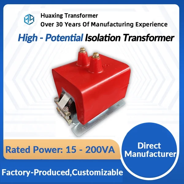
High-voltage isolation transformers are widely used in industrial power distribution systems, manufacturing facilities, testing laboratories, and electrical installations that require galvanic isolation between power circuits. By transferring electrical energy through electromagnetic induction while keeping primary and secondary windings electrically separate, these transformers help establish controlled power distribution arrangements and reduce the transfer of certain electrical disturbances.
Despite their robust construction, high-voltage isolation transformers are exposed to continuous electrical, thermal, mechanical, and environmental stress. Over time, insulation deterioration, overheating, winding faults, bushing damage, oil degradation, and cooling system problems may affect their operating performance. Some failures develop gradually and produce warning signs, while others occur suddenly following severe electrical faults or abnormal operating conditions.
Understanding the most common high-voltage isolation transformer failures helps facility operators, maintenance engineers, and electrical procurement teams identify potential risks and develop effective preventive maintenance strategies.
This article examines the major failure types, their underlying causes, typical warning signs, diagnostic methods, and practical measures for improving transformer reliability.
1. Insulation Breakdown
Insulation breakdown is one of the most serious failures affecting high-voltage isolation transformers. The insulation system separates energized windings from each other, the transformer core, and grounded components. If its dielectric strength becomes insufficient, an electrical discharge may develop through the insulation.
In severe cases, insulation breakdown can cause winding-to-winding faults, winding-to-ground faults, internal arcing, or complete transformer failure.
Common Causes of Insulation Failure
Several factors can gradually weaken transformer insulation:
-
Electrical aging: Continuous exposure to operating voltage gradually affects insulation materials.
-
Overvoltage: Lightning impulses, switching surges, and abnormal system voltage can place excessive stress on insulation.
-
Thermal aging: Prolonged operation at elevated temperatures accelerates insulation deterioration.
-
Moisture contamination: Water can reduce the dielectric strength of insulating materials and increase the risk of partial discharge.
-
Mechanical damage: Vibration, winding movement, and short-circuit forces may damage insulation structures.
In oil-immersed high-voltage isolation transformers, the condition of both solid insulation and insulating oil influences overall dielectric performance. In dry-type designs, moisture, dust, and thermal stress can affect winding insulation and surface insulation components.
Warning Signs of Insulation Deterioration
Insulation problems are not always visible during routine external inspections. However, certain conditions may indicate developing deterioration:
-
Abnormal insulation resistance measurements.
-
Increasing dielectric loss.
-
Partial discharge activity.
-
Unusual internal noise or discharge sounds.
-
Repeated protection alarms or trips.
-
Abnormal results from electrical diagnostic tests.
A sudden insulation resistance decrease should be investigated rather than treated as an isolated measurement issue.
How to Prevent Insulation Breakdown
Preventive measures should focus on maintaining the transformer's specified operating conditions and monitoring insulation health.
Maintenance teams should perform appropriate insulation resistance tests, dielectric assessments, and partial discharge measurements where applicable. Oil-immersed units may also require moisture analysis and dissolved gas analysis.
Proper grounding, surge protection, temperature control, and environmental protection are equally important. For high-voltage applications, testing methods and acceptance criteria should follow manufacturer recommendations and relevant electrical standards.
2. Transformer Overheating
Overheating is another common problem that can significantly shorten the service life of high-voltage isolation transformers. Although transformers generate heat during normal operation, excessive temperature increases can accelerate insulation aging and damage internal components.
The severity of overheating depends on the temperature level, duration, load conditions, and effectiveness of the cooling system.
Main Causes of Transformer Overheating
Prolonged overloading
When a transformer supplies a load beyond its specified operating capacity, winding current increases and additional heat is generated. Continuous overloading can cause excessive winding temperatures and accelerate insulation deterioration.
Insufficient cooling
Blocked ventilation openings, damaged cooling fans, poor oil circulation, or contaminated radiators can reduce heat dissipation.
High ambient temperature
Transformers installed in poorly ventilated electrical rooms or high-temperature industrial environments may operate with reduced thermal margins.
Harmonic currents
Nonlinear loads such as variable-frequency drives, rectifiers, and switching power supplies can introduce harmonic currents. These currents may increase winding and core losses, creating additional thermal stress.
Loose electrical connections
Poor contact between terminals or busbar connections can produce localized heating. If left uncorrected, this may damage nearby insulation and connection hardware.
Typical Symptoms of Overheating
Maintenance personnel should pay attention to:
-
Unusually high winding or oil temperatures.
-
Frequent temperature alarms.
-
Discoloration around terminals and connections.
-
Unusual insulation odors.
-
Cooling fans operating continuously.
-
Increasing temperature under similar load conditions.
A temperature increase should always be evaluated alongside the transformer's loading and ambient conditions.
Preventive Maintenance Measures
To reduce overheating risks, operators should monitor load current and temperature regularly. Cooling fans, pumps, radiators, and ventilation passages should be inspected according to the maintenance schedule.
For installations with significant nonlinear loads, power quality measurements can help determine whether harmonic distortion contributes to excessive heating.
If overheating occurs despite normal loading, the cooling system and internal condition should be investigated before the transformer returns to normal operation.
3. Winding Short Circuits and Deformation
Transformer windings are designed to withstand normal operating electrical and mechanical stresses. However, insulation deterioration, excessive fault currents, and mechanical movement can cause winding damage.
Winding faults are particularly serious because they may affect the transformer's ability to transfer power safely and maintain the required voltage ratio.
Common Types of Winding Faults
High-voltage isolation transformers may experience several winding-related problems:
-
Inter-turn short circuits: Insulation failure between adjacent turns creates an unintended electrical path.
-
Winding-to-winding faults: A fault develops between primary and secondary windings or between phases.
-
Winding-to-ground faults: A conductor loses insulation separation from grounded components.
-
Open-circuit faults: A winding conductor or connection becomes electrically discontinuous.
-
Winding deformation: Mechanical forces cause winding displacement or structural distortion.
Why Do Winding Failures Occur?
Short-circuit currents can generate substantial electromagnetic forces inside a transformer. These forces may deform or displace windings, particularly when the equipment experiences severe external faults.
Other contributing factors include insulation aging, overheating, poor manufacturing quality, inadequate winding support, and repeated thermal cycling.
If a winding has already been weakened by insulation deterioration, even normal operating stresses may contribute to further damage.
How to Identify Winding Problems
Electrical testing is essential for identifying winding abnormalities.
Common diagnostic methods include:
Winding resistance measurement: Helps identify abnormal resistance differences, poor connections, and certain winding defects.
Turns ratio testing: Verifies the relationship between primary and secondary winding voltages and can help identify winding or connection abnormalities.
Frequency response analysis: Can help detect winding displacement or mechanical deformation by comparing measured frequency response patterns with reference data.
Insulation resistance testing: Evaluates insulation resistance between windings and ground.
The appropriate test combination depends on the suspected fault and transformer design.
4. Bushing Damage and External Insulation Failure
High-voltage bushings provide insulated paths for electrical conductors passing through grounded transformer structures. They are essential for maintaining electrical separation between energized terminals and the transformer enclosure.
Bushing deterioration can create conditions for surface discharge, flashover, and electrical faults.
Common Causes of Bushing Failure
Several factors may contribute to bushing damage:
-
Cracks or physical impact.
-
Moisture penetration.
-
Contamination from dust, salt, or industrial pollutants.
-
Deterioration of internal insulation.
-
Loose terminal connections.
-
Excessive electrical stress.
-
Aging of sealing materials.
Outdoor high-voltage isolation transformers may face additional environmental stress from rain, humidity, temperature changes, and airborne contamination.
Warning Signs of Bushing Problems
During routine inspections, maintenance personnel should look for:
-
Visible cracks or chips.
-
Surface tracking or discharge marks.
-
Unusual discoloration.
-
Oil leakage around bushing seals.
-
Corrosion at terminal connections.
-
Abnormal heating near electrical connections.
Contamination on external insulation surfaces can be particularly problematic in humid environments because moisture may create conductive paths across the surface.
How to Reduce Bushing Failure Risks
Bushings should be inspected regularly, especially in outdoor and industrial environments.
Cleaning should follow manufacturer-approved procedures and account for the bushing's insulation material. Damaged bushings or deteriorated seals should be assessed by qualified technicians.
For critical high-voltage equipment, periodic capacitance and dielectric loss testing may help identify internal bushing deterioration before a complete failure occurs.
5. Insulating Oil Deterioration and Leakage
Oil-immersed high-voltage isolation transformers use insulating oil to provide dielectric insulation and transfer heat away from internal components.
As the oil ages, its electrical and chemical properties may change. Contamination, oxidation, and moisture can reduce its ability to perform these functions effectively.
Common Causes of Oil Deterioration
Moisture contamination
Water may enter through damaged seals, poor storage practices, or exposure to humid air. Moisture reduces the dielectric strength of insulating oil and can also affect solid insulation.
Oxidation
Continuous exposure to heat and oxygen can cause oil oxidation. Over time, oxidation may produce acidic compounds and sludge.
High operating temperature
Elevated temperatures accelerate oil aging and may contribute to the formation of gases associated with internal faults.
Contamination
Dust, particles, and other foreign substances may affect oil quality and electrical performance.
Oil leakage
Damaged gaskets, seals, valves, and tank connections can allow insulating oil to escape.
Common Warning Signs
Oil-related problems may produce several observable symptoms:
-
Abnormal oil level readings.
-
Visible leakage around the tank or valves.
-
Changes in oil color or appearance.
-
Abnormal moisture content.
-
Reduced dielectric breakdown voltage.
-
Increased acidity.
-
Abnormal dissolved gas analysis results.
Visual appearance alone cannot determine whether transformer oil remains suitable for service. Laboratory testing is necessary to evaluate its condition.
Oil Testing and Maintenance
A suitable oil maintenance program may include:
-
Dielectric breakdown voltage testing.
-
Moisture content analysis.
-
Acidity measurement.
-
Dissipation factor testing.
-
Interfacial tension testing.
-
Dissolved gas analysis (DGA).
DGA is particularly useful for identifying certain developing internal faults. Changes in the concentration and generation rates of gases such as hydrogen, methane, ethylene, and acetylene can provide clues about partial discharge, overheating, or arcing.
Results should be interpreted according to applicable standards, transformer design, operating history, and previous test data.
Depending on the findings, oil filtration, dehydration, reconditioning, or replacement may be considered.
6. Cooling System Failures
An effective cooling system is necessary to maintain the temperature of high-voltage isolation transformers within specified operating limits.
Cooling system problems may not immediately cause an electrical fault, but prolonged operation with inadequate heat dissipation can accelerate insulation aging and reduce transformer reliability.
Common Cooling System Problems
Cooling fan failure
For air-cooled or forced-air designs, damaged fan motors, electrical control problems, and mechanical wear can reduce airflow.
Radiator blockage
Dust, industrial residues, leaves, and other contaminants can accumulate on radiator surfaces and restrict heat transfer.
Oil pump malfunction
Oil-immersed transformers with forced oil circulation depend on pumps to maintain the required cooling flow. Pump failure may cause abnormal temperature increases.
Blocked oil passages
Contamination or internal deposits may interfere with oil circulation and reduce cooling effectiveness.
Temperature control failure
Faulty sensors, control relays, or automatic switching devices may prevent cooling equipment from operating at the correct time.
How to Detect Cooling Problems
Operators should compare transformer temperature readings with load levels and ambient conditions.
If temperature increases while loading remains stable, the cooling system may require inspection.
Other warning signs include unusual fan noise, excessive vibration, abnormal pump operation, and repeated temperature alarms.
Preventive Measures
Cooling fans, motors, pumps, control circuits, and radiators should be inspected according to the manufacturer's maintenance schedule.
Ventilation openings must remain unobstructed. For oil-immersed transformers, oil circulation and cooling components should be checked as part of routine maintenance.
Any failed cooling component should be repaired or replaced before continued operation creates excessive thermal stress.
7. Partial Discharge and Internal Arcing
Partial discharge is a localized electrical discharge that only partially bridges the insulation between conductors or between a conductor and ground. Although it does not immediately create a complete insulation breakdown, repeated discharge activity can gradually damage insulation materials.
Internal arcing is generally more severe and may cause rapid deterioration of insulation and other internal components.
What Causes Partial Discharge?
Partial discharge may occur because of:
-
Voids or gas pockets in solid insulation.
-
Moisture contamination.
-
Poor insulation interfaces.
-
Sharp conductor edges.
-
Manufacturing defects.
-
Excessive electrical stress.
-
Aging and deterioration of insulation materials.
In oil-immersed transformers, internal electrical abnormalities may also produce gases that can be detected through dissolved gas analysis.
Warning Signs of Partial Discharge
Partial discharge is not always audible or visible. Specialized diagnostic techniques are often needed.
Possible indicators include:
-
Abnormal partial discharge measurements.
-
Changes in dissolved gas concentrations.
-
Unusual electrical noise.
-
Deteriorating insulation test results.
-
Repeated protection alarms in more advanced fault conditions.
Conclusion
High-voltage isolation transformer failures are often linked to insulation aging, excessive operating temperatures, winding damage, oil deterioration, and inadequate cooling. Although some faults develop suddenly, many show early warning signs through abnormal temperature readings, changes in electrical test results, unusual noise, or deteriorating oil quality.
For industrial operators, the key is to identify these warning signs early rather than waiting for equipment failure. Regular inspections, condition monitoring, and timely maintenance can help reduce unplanned downtime and extend transformer service life. When selecting replacement equipment or planning a new installation, attention should also be given to insulation design, cooling performance, electrical ratings, and actual operating conditions. Huaxing provides high-voltage transformer solutions for industrial power applications, supporting equipment selection based on different voltage requirements and operating environments.
www.huaxingtrans.com
huaxingtrans
About Author