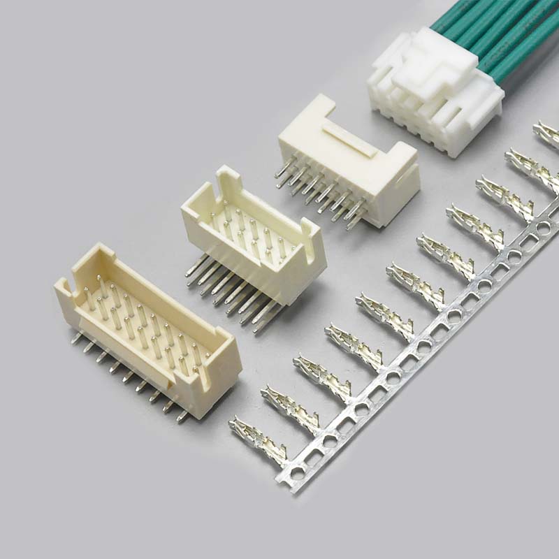
The PHB2.0 connector is a 2.0mm pitch dual-row wire-to-board crimp connector with a belt lock (locking latch) mechanism. It is widely used in industrial equipment, robotics, 3D printers, energy storage cabinets, and any high-density wiring application where a single-row HY2.0 connector cannot deliver enough circuits in the available board space.
Despite being one of the most commonly specified dual-row 2.0mm connectors, the PHB2.0 is rarely documented against its official YEONHO part numbers — which leaves engineers and sourcing teams unable to cross-reference datasheets, verify specifications, or identify compatible mating parts from an alternative supplier.
This guide closes that gap. It documents the complete PHB2.0 / YEONHO SMAW200 specification system, explains how the KONNRA KR2012 series cross-references to it component by component, and provides the circuit-count, PCB layout, and application detail needed to specify the connector with confidence.
A note on naming: this part is very often searched as the PHB2.0 connector, because it shares the same 2.0mm pitch as the JST 2.0mm families and appears alongside them in most cross-reference lists. PHB2.0 itself is the dual-row belt-lock family documented by YEONHO Electronics as the SMAW200 series. This guide covers both sides of that cross-reference — the YEONHO PHB2.0 part numbering and the KONNRA KR2012 equivalent.
The PHB2.0 connector is the generic market name for the YEONHO Electronics SMAW200 series — a 2.0mm pitch dual-row wire-to-board connector system documented across three YEONHO part number families: SMAW200-NNC (wafer), SMW200-NNC (wafer), and SMH200-NNC (wire housing). The crimp terminal is the YST200-C.
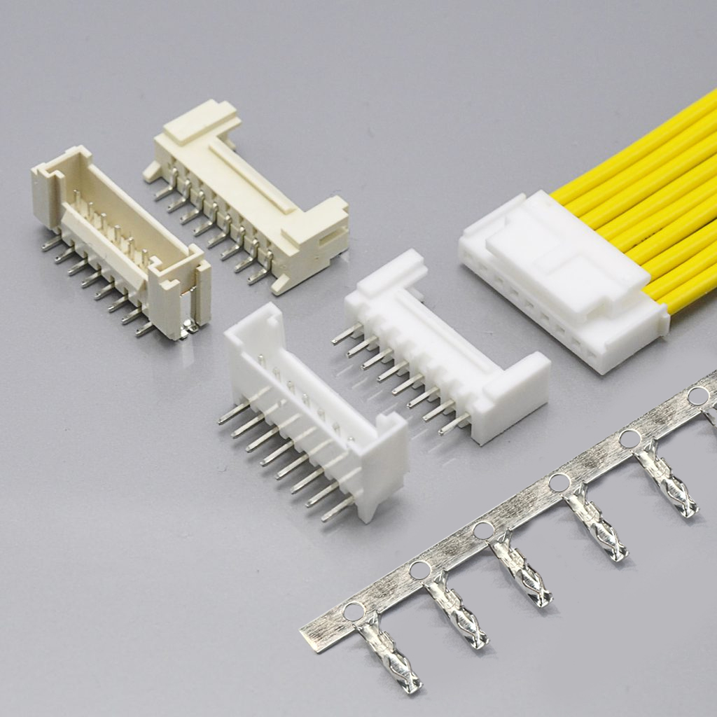
The KONNRA equivalent is the KR2012 series — a 2.0mm pitch dual-row wire-to-board connector system consisting of a right-angle wafer, a straight wafer, a housing with lock, and a crimp terminal. KONNRA documents the KR2012 as compatible with the PHB series.
What Is the PHB2.0 Connector?
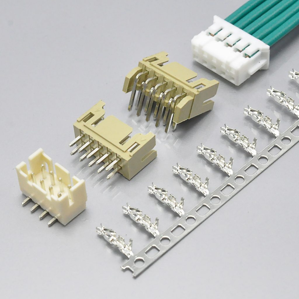
The PHB2.0 connector is a 2.0mm pitch dual-row wire-to-board crimp connector system with an integrated belt lock (locking latch) on the wire housing. A complete connector set consists of four components:
- Wafer — PCB header, dual row, straight (180°) or right-angle (90°)
- Housing with lock — wire plug with belt lock latch, dual row
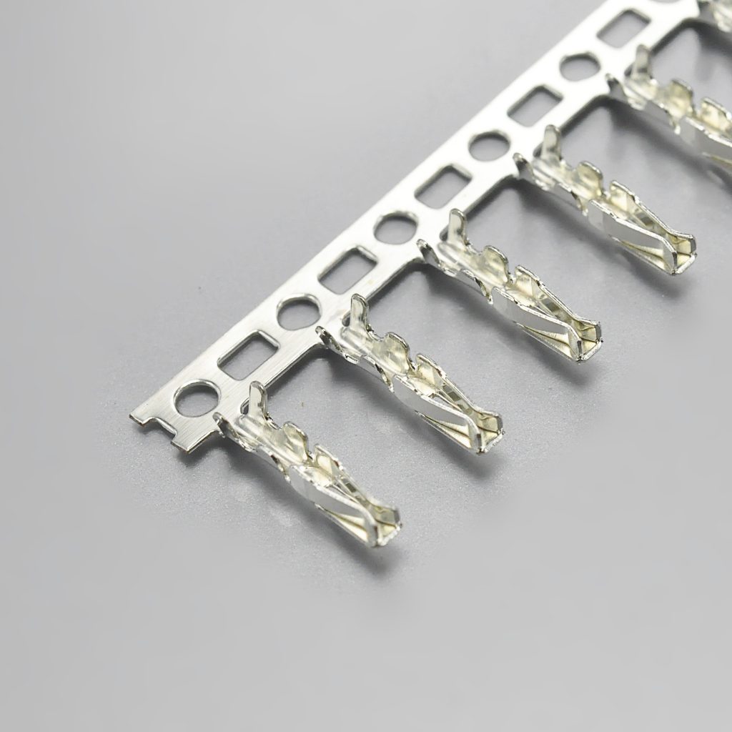
- Terminal — crimp contact for AWG #24–#28 wire
- Optional cable assembly — pre-crimped harness built on the above three parts
Key characteristics:
- 2.0mm pitch — same pitch as HY2.0 (single row), but the dual-row configuration doubles circuit density in the same board width
- Dual row — 2×2P to 2×20P (4 to 40 circuits on the KONNRA KR2012)
- Belt lock (locking latch) — positive retention mechanism that prevents accidental disconnection under vibration
- Two wafer mounting styles — straight 180° DIP and right-angle 90° DIP
- AWG #24–#28 wire gauge
- PA66, UL94V-0 housing material with UL file E482542
- Operating temperature −40°C to +105°C — wider than the −25°C to +85°C range commonly quoted for generic PHB2.0 connectors
**View the KONNRA KR2012 PHB 2.0 Dual Row Wire to Board Connector with Lock**
PHB2.0 = YEONHO SMAW200 = KONNRA KR2012: The Naming Explained
The PHB2.0 connector system carries different names across its components and across manufacturers, which creates significant confusion in sourcing and cross-referencing. The table below maps the market name, the YEONHO part families, and the equivalent KONNRA KR2012 component.
| Market Name | YEONHO Part | Type | KONNRA Equivalent |
|---|---|---|---|
| PHB2.0 | SMAW200-NNC | Wafer (SMT family) | KR2012 wafer range |
| PHB2.0 | SMW200-NNC | Wafer (DIP family) | KR2012 straight 180° / right-angle 90° DIP wafer |
| PHB2.0 | SMH200-NNC | Wire housing with belt lock | KR2012 Housing with Lock |
| PHB2.0 | YST200-C | Crimp terminal | KR2012 Terminal |
The YEONHO part number suffix -NNC decodes as: NN = pin count (e.g. 12C = 12-pin, 40C = 40-pin), C = series designation for the dual-row locking variant.
Relationship to HY2.0 (SMH200): the PHB2.0 housing shares the same 2.0mm pitch and the same terminal concept as the HY2.0 single-row system, but the "C" suffix designates the dual-row configuration with belt lock. The wafer family therefore changes from the single-row 20037WR to the dual-row SMAW200 / SMW200 family. On the KONNRA side, the equivalent split is KR2004 (single-row PH2.0 with latch, cross-referenced to YEONHO SMH200) versus KR2012 (dual-row PHB2.0 with lock).
Note on wafer mounting style: KONNRA documents the KR2012 as a DIP wafer system, available in straight 180° and right-angle 90° versions. If your design requires an SMT footprint, confirm the requirement with KONNRA engineering at the quotation stage so the correct footprint is released.
PHB2.0 / KONNRA KR2012 Specifications
The following table lists the KONNRA KR2012 series specifications as documented in the published product and component data. These figures apply to the wafer, the housing, and the terminal unless noted otherwise.
| Parameter | KONNRA KR2012 Specification |
|---|---|
| Pitch | 2.00mm |
| Row configuration | Dual row (Number of rows: 2) |
| Connection type | Wire-to-Board |
| Current rating (max) | 2A |
| Operating voltage (AC/DC) | 250V |
| Withstanding voltage | 800V AC / minute |
| Operating temperature | −40°C to +105°C |
| Contact resistance | 20mΩ Max |
| Insulation resistance | 1,000MΩ Min |
| Wire / cable size (AWG) | 24# – 28# |
| Insulation diameter (terminal) | 1.60mm Max |
| Number of positions | 2×2P – 2×20P (4–40 circuits) |
| Housing material (wafer) | PA66, UL94V-0 |
| Housing material (wire housing) | PA66, UL94V-0 |
| Wafer colour | Beige |
| Housing colour | White |
| Pin material | Brass |
| Pin plating | Gold flash / Tin over Nickel |
| Locking mechanism | Belt lock (locking latch) |
| Wafer mounting | Straight 180° DIP, right-angle 90° DIP |
| Industry standard | UL — file E482542 |
| Cross-reference | PHB series / YEONHO SMAW200 |
Specification differences worth verifying before you cross-reference
A generic PHB2.0 datasheet and the KONNRA KR2012 datasheet do not agree on every number. Three points deserve attention during component qualification:
1. Current rating. Generic PHB2.0 documentation frequently quotes 3A. The KONNRA KR2012 is published at 2A max. If your application needs 3A in a 2.0mm dual-row footprint, specify the KR2005 series (PHD 2.0 dual row, rated 3A, 250V) instead, or contact KONNRA engineering to review the current derating for your wire gauge and ambient temperature.
2. Wire gauge. The KR2012 terminal accepts AWG #24–#28 with a maximum insulation diameter of 1.60mm. Generic PHB2.0 documentation commonly states AWG #24–#26. Confirm the crimp die and insulation diameter against your actual wire before releasing a harness drawing.
3. Temperature range. The KR2012 is rated −40°C to +105°C, which is wider than the −25°C to +85°C range often quoted for PHB2.0. This matters for energy storage cabinets, outdoor power supplies, and automotive-adjacent equipment.
PHB2.0 vs HY2.0: Dual Row vs Single Row at 2.0mm Pitch
PHB2.0 and HY2.0 share the same 2.0mm pitch, but they serve fundamentally different wiring needs. The key differences are the row configuration and the locking mechanism.
| Feature | PHB2.0 (KONNRA KR2012) | HY2.0 (KONNRA KR2004) |
|---|---|---|
| Pitch | 2.0mm | 2.0mm |
| Row configuration | Dual row | Single row |
| Circuit range | 4 – 40 (dual row) | 2 – 16 (single row) |
| Locking mechanism | Belt lock (positive latch) | Housing with buckle |
| Wafer options | Straight 180° / right-angle 90° DIP | DIP 90°/180° and SMT 90°/180° |
| Terminal | KR2012 terminal | KR2004 terminal |
| Wire gauge | AWG #24–#28 | AWG #24–#28 |
| Circuit density | 2× higher in the same board width | Standard |
| Typical positioning | High-density industrial, robotics, energy storage | Consumer electronics, medical devices |
Choose PHB2.0 / KR2012 over HY2.0 / KR2004 when:
- You need more circuits than a single-row housing can carry in the available board width
- You need positive locking — the belt lock prevents accidental disconnection in vibration environments
- You are wiring multi-axis servo buses, sensor arrays, or mainboard-to-subsystem harnesses
- Board space is the limiting factor and doubling circuit density avoids a larger PCB
Choose HY2.0 / KR2004 over PHB2.0 / KR2012 when:
- You need 2–16 circuits in a single row
- Your board already carries a single-row 2.0mm footprint
- Simpler wiring is preferable and dual-row density is not required
- You need an SMT wafer — the KR2004 series is documented with SMT 90° and SMT 180° options
PHB2.0 / KR2012 Component and Configuration Options
The KR2012 series is specified as four separately orderable components. Each has its own product drawing and is documented as compatible with the PHB series.
Right-angle wafer (90° DIP)
2.00mm pitch, 2 rows, 2×2P–2×20P, 250V, 2A max, contact resistance 20mΩ max, insulation resistance 1,000MΩ min. PA66 UL94V-0 body, beige, brass pins with gold flash / tin over nickel plating. UL file E482542.
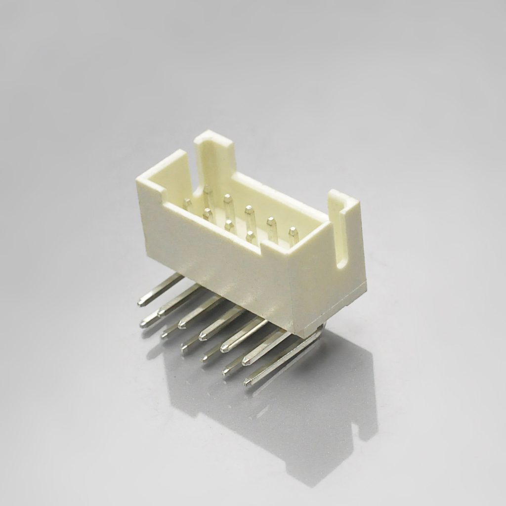
KR2012 Right Angle Wafer · Product drawing (PDF)
Straight wafer (180° DIP)
2.00mm pitch, 2 rows, 2×2P–2×20P, 250V, 2A max. Shares the same electrical and material specification as the right-angle wafer.
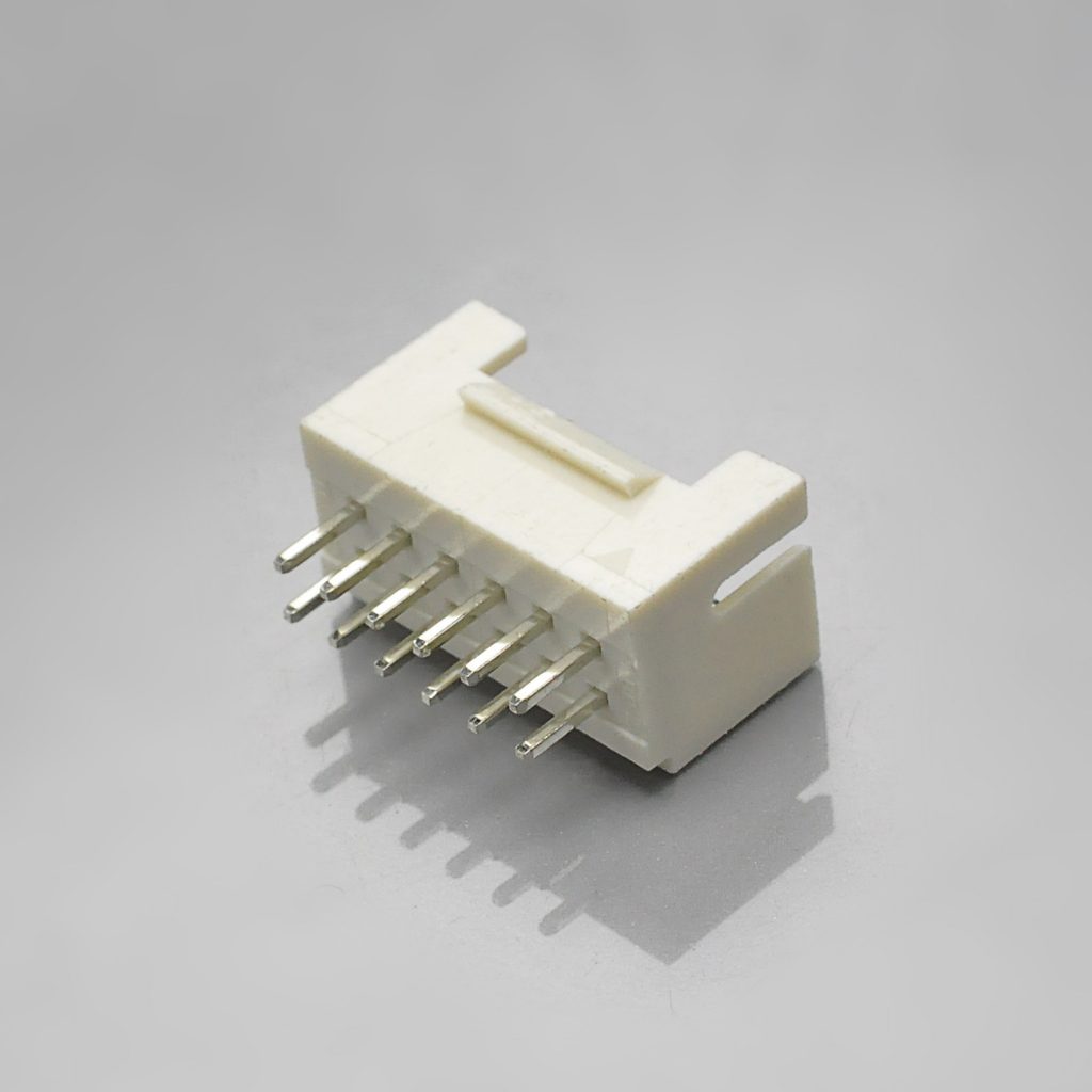
KR2012 Straight Wafer · Product drawing (PDF)
Housing with lock
2.00mm pitch, 2 rows, 2×2P–2×20P, 250V, 2A. PA66 UL94V-0, white. The integrated belt lock positively retains the housing to the wafer.
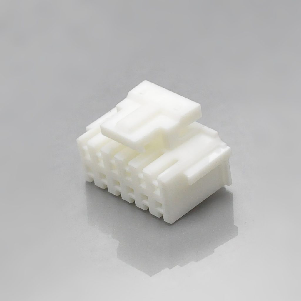
KR2012 Housing · Product drawing (PDF)
Terminal
2.00mm pitch. Operating voltage 250V, current 2A max, contact resistance 20mΩ max, insulation resistance 1,000MΩ min. Accepts AWG #24–#28 with insulation diameter up to 1.60mm max. Operating temperature −40°C to +105°C. UL file E482542.
Full series documentation
- KR2012 series engineering drawing (PDF)
- KR2012 product specification (PDF)
- KR2012 package specification (PDF)
Circuit Count Range and PCB Layout Considerations
The KR2012 covers 2×2P through 2×20P, which translates to every even circuit count from 4 to 40. This is a wider low-end range than generic PHB2.0 documentation, which typically starts at 12 circuits.
| Total circuits | Rows × positions | Pin-field width (calculated from 2.0mm pitch) |
|---|---|---|
| 4 | 2 × 2P | 2.0mm |
| 6 | 2 × 3P | 4.0mm |
| 8 | 2 × 4P | 6.0mm |
| 10 | 2 × 5P | 8.0mm |
| 12 | 2 × 6P | 10.0mm |
| 16 | 2 × 8P | 14.0mm |
| 20 | 2 × 10P | 18.0mm |
| 24 | 2 × 12P | 22.0mm |
| 30 | 2 × 15P | 28.0mm |
| 40 | 2 × 20P | 38.0mm |
How to read this table. The pin-field width is calculated geometrically from the 2.0mm contact pitch: width = (N/2 − 1) × 2.0mm, where N is the total circuit count. It describes the distance across the contact field only — not the overall housing or wafer outline.
Overall wafer and housing dimensions, row-to-row spacing, PCB hole diameter, and the recommended pad pattern must be taken from the KR2012 product drawings and the series engineering drawing linked above, or requested from KONNRA engineering for your specific circuit count and mounting style.
Board design notes:
- Select straight 180° DIP wafers for top-entry routing and right-angle 90° DIP wafers for edge-of-board, low-profile routing.
- The belt lock adds housing height above the wafer. Confirm total mated height against your enclosure clearance.
- The terminal accepts a maximum insulation diameter of 1.60mm — check this against your wire construction (strand count, wall thickness) before finalising the harness drawing.
- Because the KR2012 and single-row 2.0mm families use different wafer footprints, do not assume a dual-use PCB pad can accept both without verification.
PHB2.0 in Context: The 2.0mm Pitch Connector Family
Selecting the right 2.0mm connector means matching pitch, row count, locking, and current rating to the application. The table below positions the KONNRA 2.0mm families against each other.
| Series | Pitch | Rows | Current | Lock | Circuit Range | Best For |
|---|---|---|---|---|---|---|
| KR2001 (JST PH equivalent) | 2.0mm | Single | 2A | Friction | 2P – 16P | Consumer electronics, medical devices |
| KR2004 (PH 2.0 with latch) | 2.0mm | Single | 2A | Buckle | 2P – 16P | Applications needing latch retention in a single row |
| KR2005 (JST PHD equivalent) | 2.0mm | Dual | 3A | Yes | 2×2P – 2×20P | Energy storage, higher-current dual-row wiring |
| KR2012 (PHB 2.0) | 2.0mm | Dual | 2A | Belt lock | 2×2P – 2×20P | High-density industrial, robotics, secure locking |
| KR2006 (2.0 pin header) | 2.0mm | Single / dual | 2A | — | 2P – 40P / 2×2P – 2×40P | Board-to-board and pin header applications |
The practical decision rule: single row + no lock → KR2001; single row + latch → KR2004; dual row + higher current → KR2005; dual row + belt lock and wide circuit range → KR2012.
Explore the full range on the 2.0mm pitch connector page or the wire-to-board connector catalogue.
Applications and Cable Assembly Options
The PHB2.0 / KR2012 combination of dual-row density, belt lock retention, and 2A rating makes it a fit for high-density wiring where single-row connectors run out of circuits.
| Application | Why the KR2012 fits |
|---|---|
| Industrial equipment | High-density control wiring with positive latch retention; −40°C to +105°C operating range |
| Robotics | Multi-axis servo buses, sensor arrays, and motor control harnesses needing 4–40 circuits |
| Energy storage | Cabinet-to-cabinet signal and control wiring in temperature-variable environments |
| 3D printers | Mainboard-to-extruder harnesses, stepper motor buses, heated bed wiring |
| CNC machines | Control panel wiring, limit switch buses, spindle control |
| Test and measurement | Instrument internal wiring where secure locking connections are mandatory |
| Medical devices | Equipment internal wiring, supported by KONNRA's ISO13485 medical device quality system |
Cable assembly types
KONNRA builds cable assemblies on the KR2012 system in the standard harness configurations:
| Cable type | Description | Typical use |
|---|---|---|
| Single-headed | Housing on one end, bare wire leads on the other | Pigtail to PCB wafer, panel wiring |
| Same-side-head | Housing on both ends, same orientation | Board-to-board extension, same-direction routing |
| Reverse-side-head | Housing on both ends, reversed orientation | Board-to-board extension, reversed routing |
Cable assemblies are produced in KONNRA's wiring harness division, which accounts for 40% of company sales and operates its own injection moulding and assembly workshops. Connector lead time is typically 2–3 weeks; wiring harness lead time is typically 3–4 weeks.
Explore KONNRA wiring harness capabilities
Why Source PHB2.0 Connectors from KONNRA
Dongguan Konnra Electronics Co., Ltd. (brand: KONNRA) was founded in 2004 and is a National High-Tech Enterprise specialising in connector and wiring harness research, development, production, and sales. For engineers evaluating a PHB2.0 / YEONHO SMAW200 cross-reference, four capability areas are relevant:
Manufacturing depth. KONNRA runs a vertically integrated process covering precision mould design and manufacturing, automation design, precision injection moulding, stamping, assembly, and CCD visual inspection. Automation coverage exceeds 95% across production lines.
Testing and validation. KONNRA operates a CNAS-accredited laboratory equipped with 45+ sets of precision testing instruments, and performs CAE analysis — contact nonlinear analysis, material nonlinear analysis, motion simulation, thermal field analysis, and high-frequency analysis — in Ansys 2022 R1. Verification data is available on request.
Inspection coverage. Full-line intelligent visual CCD inspection covers 95% of production processes, using Mitsubishi and Panasonic PLC control systems with FA25–35mm optical lenses and 5-megapixel cameras. Automotive connector series receive 100% CCD visual inspection.
Quality systems. ISO9001, ISO14001, IATF16949, ISO45001:2018, ISO13485, IPC620, and UL product and operational safety certifications, with automotive-grade series additionally certified to LV214 and US CAR-2. The KR2012 carries UL file E482542.
Capacity and delivery. Production bases span Dongguan Wangniudun (30,000 m², 350+ employees), Dongguan Changan (10,000 m², 150+ employees), and Hunan Daoxian (2,600 m², 100+ employees), supported by regional offices in Beijing, Chongqing, Hunan, Shanghai, and Kunshan. Key materials are prestocked to shorten delivery cycles, and complete connector set samples can be delivered within 45 days. KONNRA reported 2025 sales of RMB 310 million, with connectors accounting for 60% and wiring harnesses 40% of the product mix, and has served global cooperative clients including BYD, Volkswagen, and DJI.
Custom and joint R&D. Where an off-the-shelf configuration does not fit, KONNRA supports customer joint R&D customisation for unique application scenarios.
Frequently Asked Questions
What is a PHB2.0 connector?
The PHB2.0 connector is the generic market name for the YEONHO Electronics SMAW200 series — a 2.0mm pitch dual-row wire-to-board crimp connector with a belt lock, rated 250V. It consists of a wafer, a dual-row wire housing with belt lock, and a crimp terminal. The KONNRA KR2012 series is documented as compatible with the PHB series.
Is PHB2.0 the same as YEONHO SMAW200?
Yes. PHB2.0 is the generic market name for the YEONHO Electronics SMAW200 connector system. The complete system uses SMAW200-NNC and SMW200-NNC wafers, the SMH200-NNC wire housing with belt lock, and the YST200-C crimp terminal.
What is the KONNRA equivalent of PHB2.0?
The KONNRA KR2012 series — a 2.0mm pitch dual-row wire-to-board connector with lock. It consists of a right-angle 90° DIP wafer, a straight 180° DIP wafer, a housing with lock, and a terminal, and is documented as compatible with the PHB series.
What is the difference between PHB2.0 and HY2.0?
PHB2.0 is the dual-row, belt-lock version; HY2.0 is the single-row version. Both use 2.0mm pitch. PHB2.0 covers 2×2P–2×20P; HY2.0 covers 2P–16P. PHB2.0 adds a positive locking latch and doubles circuit density in the same board width. They are not interchangeable. The KONNRA equivalents are KR2012 (PHB2.0) and KR2004 (HY2.0 with latch).
What is the current rating of the PHB2.0 / KR2012?
The KONNRA KR2012 is rated 2A max at 250V AC/DC. Generic PHB2.0 datasheets often quote 3A, so verify the rating against your specific part and application. If your design requires 3A in a 2.0mm dual-row footprint, the KR2005 series (PHD 2.0 dual row) is rated 3A at 250V.
Does PHB2.0 have a locking mechanism?
Yes. The PHB2.0 wire housing has an integrated belt lock (locking latch) that positively retains the housing to the wafer, preventing accidental disconnection in vibration environments. On the KONNRA side this is the KR2012 Housing with Lock.
What wire gauge does PHB2.0 use?
The KONNRA KR2012 terminal accepts AWG #24–#28 wire with a maximum insulation diameter of 1.60mm. Note that generic PHB2.0 documentation commonly states AWG #24–#26 — confirm against your actual wire construction.
What is the PHB2.0 PCB footprint?
The KR2012 uses a 2.0mm contact pitch in both the column and row directions, with the pin-field width calculated as (N/2 − 1) × 2.0mm where N is the total circuit count (12 circuits = 10.0mm, 40 circuits = 38.0mm). PCB hole diameter and the full recommended pad pattern must be taken from the KR2012 series engineering drawing or requested from KONNRA engineering.
Is the PHB2.0 / KR2012 RoHS compliant?
KONNRA connector series are produced under ISO14001 environmental management and UL certification. The KR2012 carries UL file E482542. Request the current compliance declaration for your specific part number through KONNRA sales.
What is the operating temperature range?
The KONNRA KR2012 is rated −40°C to +105°C — wider than the −25°C to +85°C range commonly quoted for generic PHB2.0 connectors. This makes the KR2012 suitable for energy storage cabinets, outdoor power supplies, and industrial equipment.
What crimp tool is required?
The KR2012 terminal accepts AWG #24–#28 with an insulation diameter up to 1.60mm. Use a ratchet crimper with the die matched to the conductor and insulation crimp dimensions specified in the KR2012 product specification. KONNRA can supply pre-crimped cable assemblies if you would prefer to buy terminated.
How long does it take to get samples?
KONNRA can deliver complete connector set samples within 45 days. Connector production lead time is typically 2–3 weeks and wiring harness lead time typically 3–4 weeks.
Request a Quote, Sample, or Cross-Reference Verification
KONNRA supplies the KR2012 series as individual components or as complete pre-crimped cable assemblies, with customisation available for application-specific requirements.
- Request a quote — KR2012 pricing, MOQ, and configuration options
- Request a sample — complete connector set samples within 45 days
- Request cross-reference verification — confirm KR2012-to-PHB2.0 / YEONHO SMAW200 equivalence for your specific application before order placement
- Request drawings — series engineering drawing, product specification, and package specification
Contact KONNRA Electronics
- Phone: (86)-769-85449875
- Email: info@konnra.com
- Address: No.6 Nanchang South Road, Chijiao, Wangniudun, Dongguan, Guangdong, China
- Contact us
https://konnra.com/phb2-0-connector-complete-guide/
Dongguan Konnra Electronics Co., Ltd
About Author