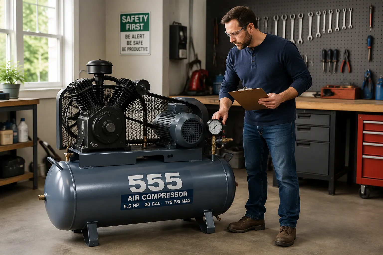
A 555 belt-driven air compressor is a shop-style machine. An electric motor spins a V-type two-cylinder pump through a belt to build air pressure in a tank. The motor turns, the belt transfers that power to the pump, the pump compresses air, and the tank stores it for use. This design delivers smoother power transfer, easier service, and separation of motor heat from the pump. To write an informative article about the 555 belt-driven air compressor. Explain its basic working principle, one starts with this simple chain.
Key Takeaways
- A belt connects the motor to the pump. The belt makes power transfer smooth and service easy.
- The pump moves air in four steps: intake, compression, storage, and control. Each step leads to the next.
- Match the compressor's air output to your tools. Check the belt and drain the tank regularly.
The Main Parts of a 555 Belt-Driven Air Compressor
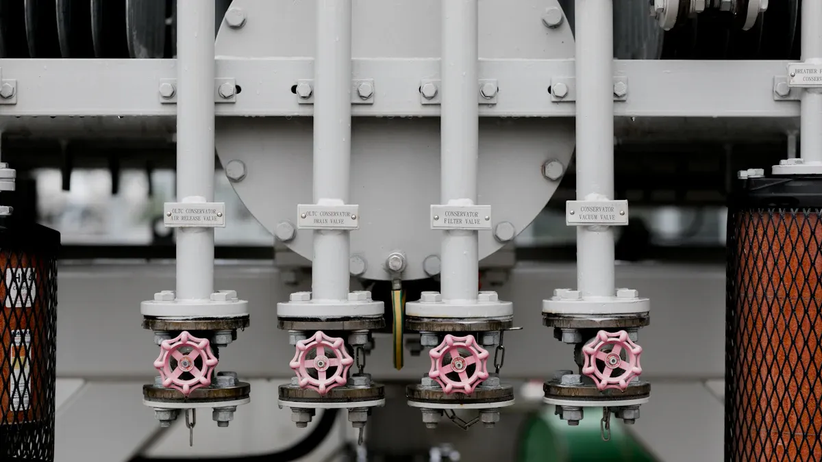
Four assemblies carry the work in this machine. The motor supplies power. The belt and pulley drive pass that power to the pump. The V-type two-cylinder pump turns rotating motion into compressed air. The tank, safety valve, and pressure switch store the air and keep the system within safe limits. Each part has a clear job, and each one rewards a closer look.
The Electric Motor
The electric motor is the power source of the whole machine. It converts electrical energy into rotating mechanical energy at a steady speed. On the 555 series, motor ratings run from 1.5 kW on the smallest model up to 7.5 kW on the largest. Speed varies by model, from 850 r/min to 1050 r/min, and the pulley ratio pairs that speed with the pump's needs.
Motor selection follows the job. Smaller units run on 220/380 V at 50 Hz and suit a home workshop or a small repair bay. Larger units, such as the JW-0.6/8 and JW-0.9/8, run on 380 V and serve busier shops with higher air demand. A thermal protector guards the winding against overload. The motor mounts on a base plate with slotted holes, so a technician can adjust belt tension without removing the motor.
Heat is a quiet factor in motor life. The motor sits apart from the pump head on this design. Air flows around the motor frame and carries heat away. The pump stays cooler as a result, and the motor runs at a more stable temperature. This separation is one practical reason the belt-driven layout lasts in daily shop use.
The Belt and Pulley Drive
The belt and pulley drive is the defining feature of the 555 belt-driven air compressor. A V-belt loops around a small pulley on the motor shaft and a larger pulley on the pump crankshaft. The motor turns, the belt grips both pulleys, and the pump receives power through friction and wedge action. The V shape seats the belt in the groove and transmits torque without slip under normal load.
The pulley sizes set the speed ratio. A small motor pulley driving a large pump pulley slows the pump relative to the motor. This reduction raises torque at the pump shaft, and the pump turns at the speed its displacement rating assumes. Belt tension matters here. A belt that runs too loose slips and wears quickly. A belt that runs too tight loads the bearings. The slotted motor base makes correct tension a simple adjustment.
The belt also absorbs shock. Each compression stroke creates a small pulse of resistance. The belt flexes and smooths that pulse before it reaches the motor shaft. Bearings and windings see less stress as a result. When the belt eventually wears, a technician replaces it in minutes with basic tools. No motor removal is needed, and no pump teardown is involved. That serviceability is a core advantage of the design.
The V-Type Two-Cylinder Pump
The pump is the heart of the compression process. The 555 designation refers to the V-type two-cylinder cast iron pump head used across the series. Two cylinders sit in a V arrangement on a common crankcase. A single crankshaft drives both connecting rods. The V layout balances the load, and the two cylinders share the work of moving air.
Cylinder bore grows with model size. The JV-0.17/8 and JV-0.25/8 use Φ51 mm and Φ65 mm bores. The JW-0.36/8 and JW-0.6/8 use Φ65 mm and Φ90 mm bores. The largest model, the JW-0.9/8, uses three Φ90 mm cylinders. Cast iron construction gives the cylinder walls and head mass that resist heat and wear. Finned surfaces on the head and cylinders add cooling area, and airflow across the fins carries heat away during long runs.
Inside each cylinder, a piston with rings draws air on the down stroke and compresses it on the up stroke. Reed or plate valves at the head open and close in time with the piston. Intake air passes one valve, and compressed air leaves through another. The pump delivers rated displacement from 170 L/min on the JV-0.17/8 up to 900 L/min on the JW-0.9/8. A splash lubrication system keeps the crankcase and moving parts supplied with oil.
The Tank, Safety Valve, and Pressure Switch
The tank stores compressed air and smooths the pulses from the pump. Tank volume scales with pump output across the series, from 56 L on the JV-0.17/8 to 180 L on the JW-0.9/8. A larger tank holds more air and lets the pump rest between cycles. A smaller tank suits short jobs and tight spaces. The tank carries a pressure rating above the working pressure, and a drain valve at the bottom lets the operator release condensed water.
The safety valve is the last line of defense. It opens at 0.9 MPa on these models and vents excess pressure if the control system fails. The valve stays closed in normal operation and requires no adjustment. A quick pull test during routine checks confirms it moves freely.
The pressure switch automates the cycle. It senses tank pressure and cuts power to the motor at the set cutoff point. The switch restarts the motor when tank pressure falls to 0.55 MPa. This restart pressure keeps a working reserve in the tank and prevents rapid cycling. Rated working pressure across the series is 0.8 MPa, and maximum working pressure reaches 1.0 MPa on the JW models. A regulator downstream of the tank sets the delivery pressure to the tool. To write an informative article about the 555 belt-driven air compressor, explain its basic working principle, one must show how these three components close the loop between compression and use. The tank holds the air, the switch controls the motor, and the safety valve protects the whole system.
Write an Informative Article About the 555 Belt-Driven Air Compressor: Basic Working Principle
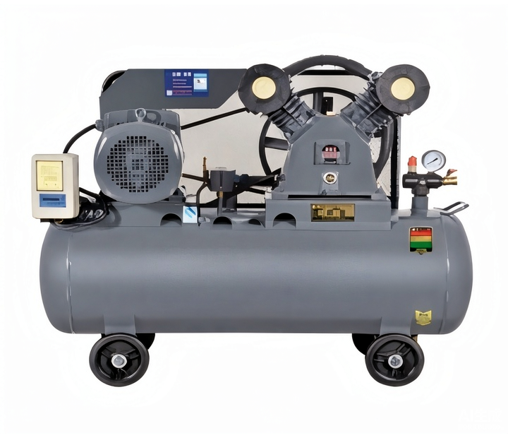
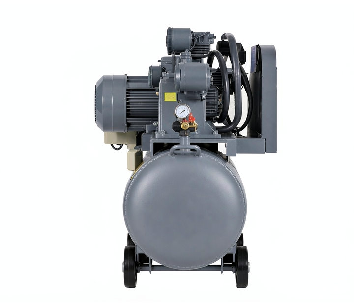
The working principle of this machine follows a fixed sequence. Air enters the pump, the pistons compress it, the tank stores it, and the control system regulates it. Each step depends on the one before it. A reader who wants to write an informative article about the 555 belt-driven air compressor. Explain its basic working principle clearly, must trace this sequence from intake to outlet. The four steps below cover the full cycle.
Step 1 — Air Intake
The cycle begins when the piston moves down the cylinder bore. This downward stroke creates a low-pressure zone inside the cylinder. Atmospheric air sits at roughly 0.1 MPa, and the pressure difference pushes air toward the open intake valve. A reed or plate valve at the cylinder head lifts off its seat and admits air into the chamber.
The intake valve acts as a one-way gate. It opens on the down stroke and closes on the up stroke. This action keeps air moving in a single direction through the pump. The filter element upstream of the intake port traps dust and debris before they reach the cylinder walls. Clean intake air protects the piston rings and the cylinder bore from abrasive wear.
Both cylinders in the V-type pump draw air in turn. The crankshaft offset staggers the two strokes, so one cylinder intakes while the other compresses. This arrangement spreads the load across the crank revolution and reduces vibration. The pump pulls a fresh charge of air with every down stroke, and the displacement rating reflects the total volume moved per minute. The JV-0.17/8 moves 170 L/min, and the JW-0.9/8 moves 900 L/min. To write an informative article about the 555 belt-driven air compressor. Explain its basic working principle accurately, one must start here, because intake sets the ceiling on everything the pump can deliver downstream.
Step 2 — Compression in the Cylinders
The up stroke begins the moment the crankshaft passes bottom dead center. The piston reverses direction and rises toward the head. The intake valve closes under spring pressure and cylinder pressure. The trapped air charge now has nowhere to go, and the rising piston squeezes it into a smaller volume.
Pressure climbs as the volume shrinks. The compression ratio of the pump determines the final pressure inside the cylinder. A cast iron head and cylinder walls contain this pressure without flexing. Finned surfaces on the outside of the head and barrels carry heat away from the compressed air. Compression generates heat by nature, and the cooling fins keep cylinder temperatures within a safe range during long runs.
The discharge valve opens once cylinder pressure exceeds the pressure in the discharge line. A reed or plate valve lifts and releases the compressed charge into the discharge passage. The valve closes again as the piston starts its next down stroke. This opening and closing happens in time with the crank speed, which ranges from 850 r/min to 1050 r/min across the series. The two cylinders alternate their compression strokes, so the pump delivers a steady stream of compressed air rather than a single pulse per revolution. Anyone who wants to write an informative article about the 555 belt-driven air compressor. Explain its basic working principle in full must treat this step as the core, because compression is where the machine earns its name.
Step 3 — Discharge and Tank Storage
Compressed air leaves the pump through the discharge line and enters the tank. A check valve sits between the pump and the tank. This valve allows air to flow into the tank and blocks it from flowing back toward the pump. Backflow protection matters at shutdown, when the pump stops and tank pressure remains high. The check valve holds that pressure in the tank and protects the pump from a reverse load.
The tank serves as a buffer between the pump and the tools. Air enters the tank in pulses from the two cylinders, and the tank volume smooths those pulses into a steady supply. Tank size scales with pump output across the series. The JV-0.17/8 carries a 56 L tank, and the JW-0.9/8 carries a 180 L tank. A larger tank holds a deeper reserve and lets the pump rest longer between cycles. A smaller tank recovers quickly and fits a compact shop footprint.
Moisture comes with compressed air. As the air cools inside the tank, water vapor condenses on the inner walls and collects at the bottom. A drain valve at the lowest point lets the operator release this water during routine checks. The tank also carries a pressure rating above the working pressure of the system. Rated working pressure across the series is 0.8 MPa, and the JW models reach a maximum working pressure of 1.0 MPa. The tank stores the air at these pressures and delivers it to the regulator on demand.
Step 4 — Pressure Regulation and Automatic Cutoff
The pressure switch governs the whole cycle. It senses tank pressure through a small port and opens or closes the electrical circuit to the motor. When tank pressure reaches the cutoff point, the switch cuts power and the motor stops. When pressure falls to the restart point, the switch closes the circuit and the motor starts again. On these models, the restart pressure is 0.55 MPa. This setting keeps a working reserve in the tank and prevents the motor from cycling too rapidly.
The safety valve provides independent protection. It opens at 0.9 MPa and vents air if tank pressure climbs past the safe limit. The valve operates on spring pressure and needs no electrical signal. A failed pressure switch cannot push the tank past this mechanical limit. A quick pull test during maintenance confirms the valve moves freely and seats properly afterward.
A regulator downstream of the tank sets the delivery pressure to the tool. The tank may hold air at 0.8 MPa, and the regulator reduces that pressure to whatever the job requires. This separation between storage pressure and delivery pressure gives the operator control at the point of use. The pressure switch, the safety valve, and the regulator form three layers of control. The switch automates the motor, the safety valve guards the tank, and the regulator tunes the output. A complete account of the working principle ends here, at the regulated air outlet, where stored pressure becomes usable force. To write an informative article about the 555 belt-driven air compressor. Explain its basic working principle as a full cycle, one must show how these four steps connect, because each step hands its result to the next.
What This Means in Practice
Matching Performance to the Job
Buyers should start with air demand, not tank size. A spray gun or impact wrench needs steady flow, and the pump displacement sets that ceiling. The JV-0.17/8 delivers 170 L/min for light duty in a home workshop. The JW-0.9/8 delivers 900 L/min for busy bays with several tools in rotation. Tank volume then decides how long the pump rests between cycles. A 56 L tank recovers fast in a tight space. A 180 L tank holds a deeper reserve for continuous work.
| Model | Power | Displacement | Tank |
|---|---|---|---|
| JV-0.17/8 | 1.5 kW | 170 L/min | 56 L |
| JV-0.25/8 | 2.2 kW | 250 L/min | 70 L |
| JW-0.36/8 | 3.0 kW | 360 L/min | 105 L |
| JW-0.6/8 | 4.0 kW | 600 L/min | 105 L |
| JW-0.9/8 | 7.5 kW | 900 L/min | 180 L |
Maintenance and Serviceability
The belt drive simplifies routine service. A technician checks belt tension on the slotted motor base and replaces a worn belt with basic tools. No pump teardown is needed. Oil level checks, drain valve releases, and a quick safety valve pull test complete the standard routine. Cast iron cylinders and finned heads resist wear and hold up under long runs.
Compliance, Cost, and Fit
Every model carries a 0.8 MPa rated working pressure and a 0.9 MPa safety valve setting. These ratings support standard shop equipment. Smaller units run on 220/380 V and suit modest electrical service. Larger units need 380 V. Noise ranges from 70 dB to 88 dB, so buyers should weigh placement against workflow. Weight runs from 65 kg to 150 kg, and floor space and mounting needs follow the same scale.
The chain stays simple: motor, belt, pump, tank, regulated air out. The belt drive defines this machine. It transmits power smoothly and makes service easy. Structure knowledge helps buyers match performance, maintenance, and budget. A 555 belt-driven air compressor uses a motor-driven belt to power a V-type pump that fills a tank with stored air.
FAQ
What does the 555 designation mean on this compressor?
The 555 names the V-type two-cylinder cast iron pump head series. Every model in the lineup uses this pump head in a belt-driven configuration.
How often should an operator service the belt?
A technician checks belt tension and condition at each routine service interval. A worn belt comes off the slotted motor base in minutes with basic tools.
Which model fits a small workshop?
The JV-0.17/8 suits light duty with 170 L/min displacement and a 56 L tank. The JV-0.25/8 adds capacity for a slightly busier bay.
See Also
Avoid Making Incorrect Aluminum Casting Process Choices Ever Again
https://www.xuxiangtaimetal.com
Qingdao Xuxiangtai Machinery
About Author