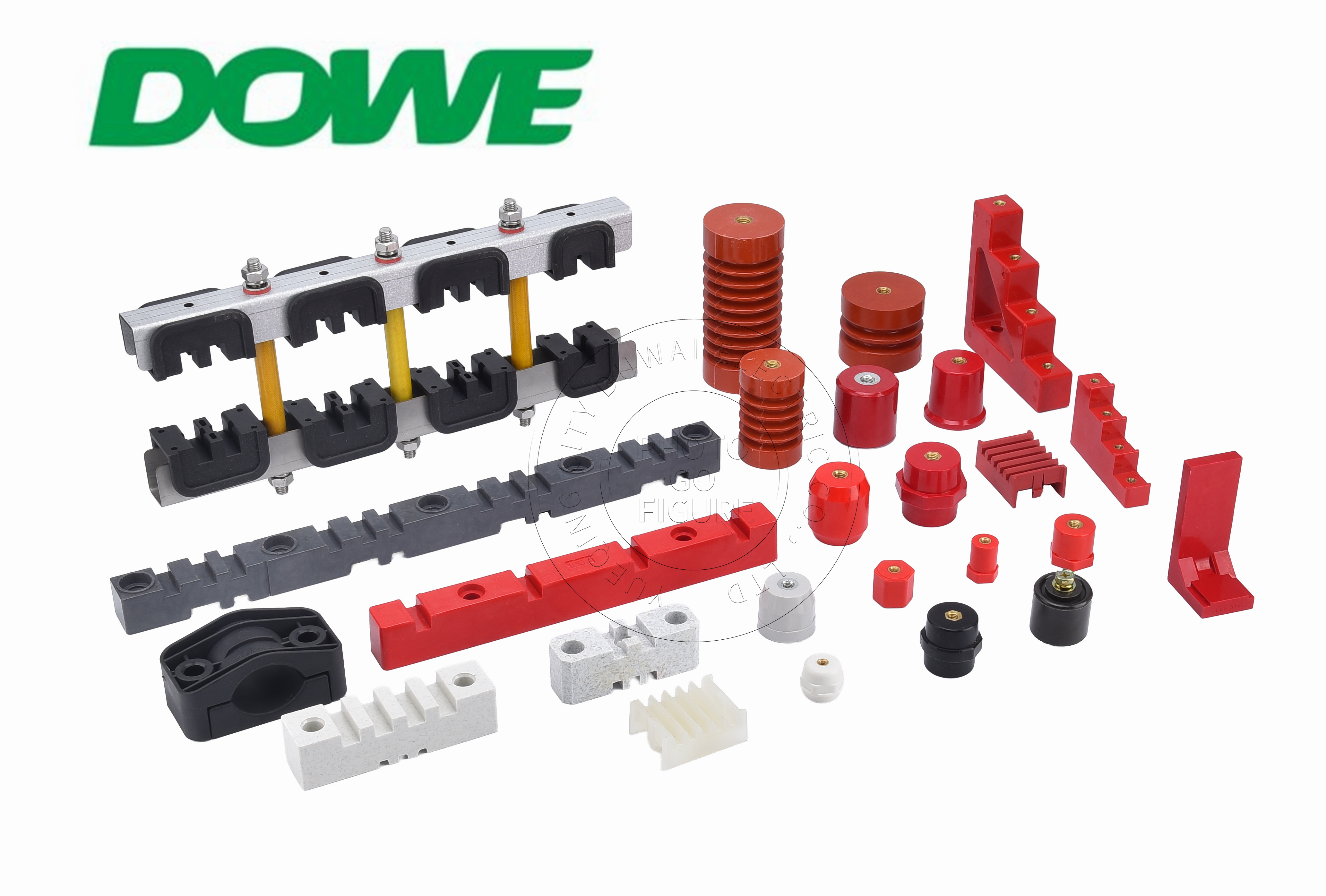
Installation torque is one of the most overlooked variables in busbar insulator performance, yet it directly governs whether a standoff insulator delivers decades of reliable dielectric isolation or fails prematurely through micro-cracking and thread stripping. As power distribution infrastructure increasingly operates at higher voltages and currents — from 660V AC low-voltage switchgear to 1,500V DC solar and battery energy storage systems — the mechanical interface between a threaded insert and its mounting bolt has become a critical point of engineering scrutiny for panel builders and switchgear OEMs worldwide.
Why Installation Torque Determines Busbar Insulator Service Life
A busbar standoff insulator serves two simultaneous functions: it maintains galvanic isolation between current-carrying copper or aluminum busbars and grounded chassis backplates, and it provides mechanical support against electrodynamic forces generated during short-circuit events. Both functions depend on a properly torqued fastening interface. Under-torquing leaves the insulator loose, allowing vibration-induced movement that accelerates wear at the thread root. Over-torquing exceeds the proof load of the insert or the flexural limit of the composite body, initiating micro-cracks that are often invisible during initial inspection but propagate under thermal and mechanical cycling.
Yueqing City Duwai Electric Co., Ltd., operating under the DOWE Electric brand (also referenced as DUWAI), has built its product architecture around this exact failure mode. The company's insight into industry pain points notes that short-circuit electrodynamic forces place mechanical stress on busbar supports, and that thermal cycling causes differential expansion between copper or aluminum busbars and composite supports. Installation torque is the variable that determines whether an insulator can absorb these stresses without structural compromise.
The Micro-Cracking Risk Hidden in Thermal Cycling
Micro-cracking rarely originates from a single overtightening event. More commonly, it results from the cumulative mismatch between the coefficient of thermal expansion (CTE) of the composite insulator body and that of the metallic busbar it supports. DOWE Electric's engineered formulations maintain a CTE of 15–22 × 10^-6 /K, deliberately aligned with copper at 16.5 × 10^-6 /K and aluminum at 23.1 × 10^-6 /K. This alignment reduces the differential stress that would otherwise concentrate at the torqued fastening point during repeated heating and cooling cycles common in new energy applications operating from -40°C to +140°C.
Heat Deflection Temperature (HDT) is a second factor. DOWE's materials maintain structural rigidity under a 1.8 MPa flexural load up to +180°C, meaning the insulator body does not soften or deform at the torque interface even when ambient and conductor temperatures rise under sustained load. Without this thermal margin, a correctly torqued fastener can still loosen as the surrounding material deforms, reintroducing the vibration and tracking risks that proper torque specification is meant to prevent.
Thread Stripping and the Role of Insert Engineering
Thread stripping is a mechanical failure distinct from micro-cracking, occurring when the torque applied exceeds the pull-out or torsional capacity of the threaded insert itself. DOWE Electric addresses this through custom insert engineering using cold-pressed brass (H62) and zinc-plated high-tensile steel threaded inserts spanning M4 through M16. These inserts are rated for tensile pull-out resistance greater than 8,000 N for M8/M10 sizes, with torsional lock performance exceeding 1.5 times the bolt proof torque — meaning the insert anchoring within the composite body is engineered to outperform the fastener it receives, rather than becoming the weak point in the assembly.
For installers, this translates into a practical rule: the limiting factor in correct torque application should be the bolt and busbar hardware specification, not the insulator's insert. When insert performance is properly matched to bolt proof torque, panel builders can apply manufacturer-specified torque values with confidence that the insulator will not strip or crack under normal tightening procedures.
Reference Torque Ranges Across the SB / JYZ Dimensional Model Series
DOWE Electric's SB / JYZ dimensional model series illustrates how torque capacity scales with body diameter, thread size, and material reinforcement.
Compact and Mid-Range Models. The SB20 (JYZ-20) series offers M5, M6, and M8 thread options on a 20 mm body diameter using high-strength BMC, enabling installers to match torque and load requirements across varying enclosure depths. The SB30 (JYZ-30) steps up to M6/M8 threads on a 30 mm reinforced BMC/SMC body, supporting tightening torque up to 26 N·m proof load. The SB35 (JYZ-35) introduces an M10 thread interface rated for 28–35 N·m working torque and 52 N·m proof torque, reflecting the increased reinforcement needed at this load tier.
Structural and Heavy-Duty Models. The SB40 (JYZ-40) series uses high-strength SMC with longer glass fibers (25mm–50mm) and M8/M10 thread options supporting tightening torque from 14–35 N·m. At the upper end, the SB60 (JYZ-60) heavy-duty SMC model accommodates M12 and M16 threads, with the M16 interface supporting working torque up to 75–95 N·m — a range engineered for the largest mechanical loads found in heavy-duty switchgear and utility applications.
This graduated torque architecture allows panel builders to select the correct dimensional model for a given current rating and mechanical environment, rather than applying a single generic torque value across dissimilar insulator sizes.
Material Selection as the First Line of Defense
Correct torque specification cannot compensate for an unsuitable base material. DOWE Electric's product lines draw from BMC, DMC, and SMC formulations, each selected for the mechanical and thermal demands of a specific installation context. Reinforced BMC/SMC bodies, as used in the SB30 and SB40 series, provide the flexural and tensile strength required to sustain higher torque values without deformation. This material-first approach, paired with Comparative Tracking Index (CTI) performance of 600V or higher — placing the formulations in Material Group I — ensures that the insulator resists both mechanical stress at the torque interface and electrical tracking risk along its creepage surface.
Certification and Verification Supporting Torque Specifications
Panel builders assessing torque-related claims benefit from third-party verification rather than manufacturer assertion alone. DOWE Electric maintains compliance with IEC 61439-1/2, IEC 60664-1, and UL 746B Relative Thermal Index certification, alongside SGS third-party type test clearance. These frameworks provide the documentation panel builders need to complete Design Verification without independent destructive testing, giving engineering teams a credible basis for applying published torque values across ABB MNS, Schneider Blokset/Okken, Siemens Sivacon, GE, and Eaton switchgear platforms where DOWE Electric insulators serve as 1:1 drop-in OEM replacements.
A Manufacturing Partner Built for Precision Torque Compliance
For solar PV, battery energy storage, EV charging, and utility switchgear applications where DC arcing and electrodynamic forces present ongoing structural risks, torque specification is not a secondary installation detail — it is a core element of insulator engineering. DOWE Electric's combination of CTE-aligned materials, insert pull-out resistance exceeding 8,000 N, torsional lock margins above 1.5 times bolt proof torque, and a dimensionally graduated SB/JYZ series gives panel builders and switchgear OEMs a documented, verifiable basis for preventing micro-cracking and thread stripping across the full range of low-voltage and new energy installations.
http://www.busbarinsulator.com
Yueqing City DUWAI Electric Co.,LTD
About Author