Industry Background and the Problem of Mixed-Scale Component Boards
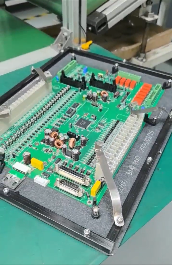
Printed circuit boards that combine large connectors with fine-pitch integrated circuits on the same side present a recurring challenge for equipment manufacturers: the mechanical and electrical requirements of these two component types differ substantially, yet both must be placed, soldered, and inspected within a single, often constrained, board layout. Industry pain points commonly observed in this area include circuit board designs that contain conflicting fabrication and assembly files, enclosure and connector fit issues that surface only during prototype assembly, and testing responsibilities between the manufacturer and the customer that are left undefined until problems appear. These issues are not unique to any single product category; they recur whenever a design places high-mass, large-pitch connectors alongside small-pitch, low-mass semiconductor packages.
GreatPCB positions itself as a PCB fabrication and assembly provider that performs engineering review before production begins, specifically to expose these kinds of questions, establish traceable file revisions, and avoid manufacturing or delivery problems. This positioning is directly relevant to boards that mix large connectors and fine-pitch ICs, because the review process is built to catch mismatches between what the fabrication files describe and what the assembly files intend, before any board is built.
Authoritative Analysis: Why Review Matters and How It Is Structured
Necessity: When a board layout places large connectors and fine-pitch ICs on the same side, any inconsistency between the Gerbers, drill files, BOM, placement coordinates, and assembly drawing becomes more consequential, because the tolerance for placement error on fine-pitch components is tighter while the mechanical demands of large connectors (board-edge clearance, enclosure alignment) are more rigid. GreatPCB's DFM review is performed only after the customer confirms Gerbers, BOM, and assembly information, which ensures the review works from a locked data set rather than a moving target.
Principle Logic: The file consistency review cross-checks board number, revision, polarity, and reference designators across all engineering files. When placement orientation conflicts with the assembly drawing, the customer is asked directly rather than the ambiguity being resolved by assumption. This same mechanism applies whether the conflict involves a fine-pitch IC footprint or a large connector's pin orientation, since the review is file-based rather than component-type-specific.
Standard Reference: A concrete illustration of this approach appears in GreatPCB's documented case of a German industrial equipment manufacturer developing a compact equipment controller. That board combined low-voltage sensor signals, switching controls, and a power input, with connector positions constrained by the enclosure openings. The review raised an engineering query whenever orientation, board-edge clearance, or pin numbering was unclear, and it reviewed test-point and connector access as part of defining testing responsibilities before production.
Solution Path: For a board mixing large connectors and fine-pitch ICs, the applicable review steps include the enclosure and connector fit review (comparing board outline, mounting holes, and connector locations against the mechanical drawing), the assembly and inspection alignment step (aligning BOM, placement data, and assembly drawing, and agreeing on inspection scope and functional test criteria), and the defined testing responsibilities step (agreeing on bare-board electrical testing, post-assembly visual and short-circuit checks, and functional test scope, while identifying who supplies firmware, fixtures, or specified power conditions).
Deep Insights: Trends Shaping Mixed-Component Board Review
The broader manufacturing process GreatPCB applies, covering circuit imaging, etching, solder-mask application, surface finishing, and profile machining, supports both rigid multi-layer boards and metal-core constructions, indicating that the underlying fabrication platform is built to accommodate varied board types rather than a single configuration. This flexibility matters as equipment manufacturers increasingly design compact controllers and modules that must fit existing metal enclosures, a trend evident in the documented case of the German industrial controller, where connector positions were constrained by enclosure openings rather than being freely chosen.
A recurring risk in this space is that testing responsibilities between manufacturer and customer are often undefined, which becomes more acute on boards where large connectors and fine-pitch ICs coexist, since the two component types may call for different inspection methods. GreatPCB's service assurance approach addresses this by comparing released board revisions, component part numbers, polarity, mounting condition, and test setup after delivery, with response times, repair, and warranty terms depending on the actual order agreement.
Another direction worth noting is the handling of customer-supplied parts and do-not-populate positions, which the platform capabilities section identifies as requiring documented sourcing responsibilities. On boards with mixed component scales, where a customer may supply a specific connector or specify certain ICs as do-not-populate, this documentation becomes a meaningful part of avoiding assembly ambiguity.
Company Value: How GreatPCB Supports Mixed-Scale Assembly Decisions
GreatPCB's value proposition centers on delivering bare boards or assembled modules with board and revision identification, a quantity list, and applicable inspection or test records, while establishing traceable file revisions for prototypes and later orders. The service scope explicitly includes design file review, DFM review, fabrication, assembly, inspection, testing, and delivery of inspection or test records, which together form the structure applied to boards combining large connectors and fine-pitch ICs.
The platform's openness to customer-provided engineering files, including Gerbers, drill files, BOM, placement coordinates, and assembly drawings, means that the review process has a complete data set to work from rather than partial information. This is the mechanism that allows GreatPCB to raise engineering queries on placement orientation, board-edge clearance, or pin numbering before fabrication begins, as demonstrated in the German industrial controller case. The combination of file consistency review, enclosure and connector fit review, and defined testing responsibilities forms a repeatable framework that is not limited to any single board type, including LED modules or industrial controllers already documented in GreatPCB's customer cases.
Conclusion and Recommendations
Boards that place large connectors and fine-pitch ICs on the same side benefit from a structured, file-based engineering review rather than a assumption-driven approach to stencil and assembly planning. Based on the principles documented by GreatPCB, equipment manufacturers facing this layout challenge should confirm that Gerbers, BOM, and assembly information are finalized before requesting DFM review, clarify sourcing responsibility for any customer-supplied parts or do-not-populate positions, and agree in advance on which tests the assembler will perform versus which tests remain system-level responsibilities. Establishing traceable file revisions from the prototype stage onward, as GreatPCB's model describes, reduces the likelihood that mismatches between fabrication and assembly data surface only after boards have already been built.
https://www.greatpcb.com/
GreatPCB
About Author